Arduino
约 1305 个字 202 行代码 4 张图片 预计阅读时间 8 分钟
资源 
Built-in Examples | Arduino Documentation
配置 
IDE 下载 
下载对应版本的 IDE 即可
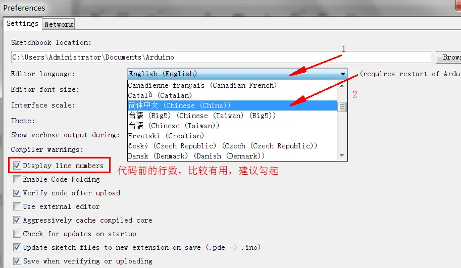
IDE 汉化 
打开 arduino,然后点击File——>Preference,按图 3 顺序点击设置,然后重启,就可以设置成中文了
IDE 库的下载和导入 
- 直接下载
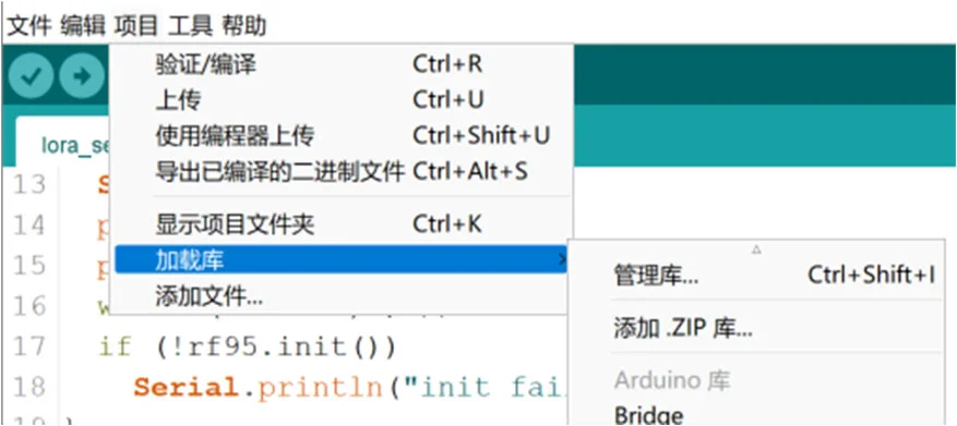
- 导入 zip 库:点击左上角“项目” -> “加载库” -> “添加 .ZIP 库”然后选择下载的 zip 文件即可
vscode 中 Arduino IDE 插件 
- 保证 Arduino IDE 下载完成
- 下载插件
 -
-
Python 固件烧录 
简单例程 
LED 闪烁 
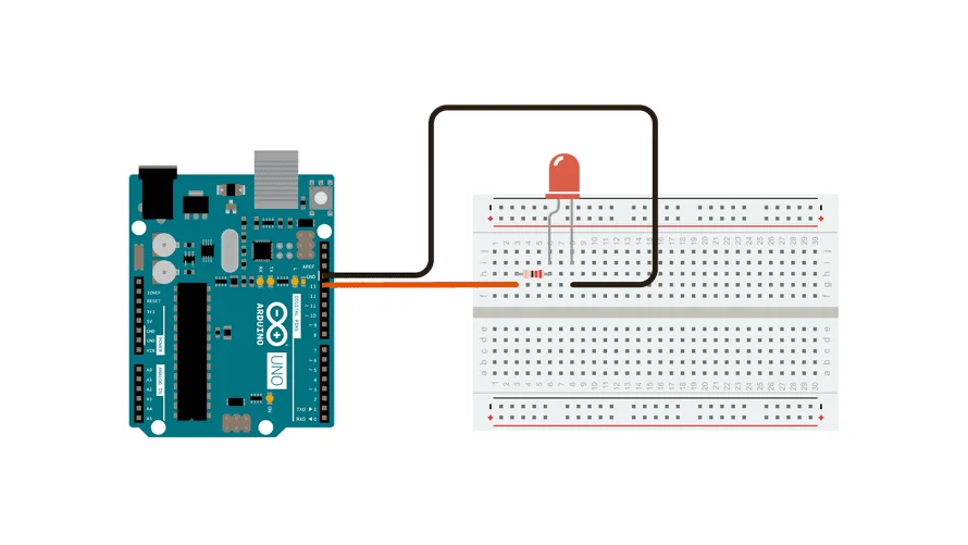
This example uses the built-in LED that most Arduino boards have. This LED is connected to a digital pin and its number may vary from board type to board type.
void setup() {
  // initialize digital pin LED_BUILTIN as an output.
  pinMode(LED_BUILTIN, OUTPUT);
}

// the loop function runs over and over again forever
void loop() {
  digitalWrite(LED_BUILTIN, HIGH);  // turn the LED on (HIGH is the voltage level)
  delay(1000);                      // wait for a second
  digitalWrite(LED_BUILTIN, LOW);   // turn the LED off by making the voltage LOW
  delay(1000);                      // wait for a second
}
int ledPin = 13;  // LED 连接到数字引脚 13

void setup() {
  pinMode(ledPin, OUTPUT);  // 设置 LED 引脚为输出
}

void loop() {
  digitalWrite(ledPin, HIGH);  // 点亮 LED
  delay(500);  // 延时 500ms
  digitalWrite(ledPin, LOW);  // 熄灭 LED
  delay(500);  // 延时 500ms
}
串口通信 
串口通信最重要的参数是波特率、数据位、停止位和奇偶校验。
串口操作函数总结 
begin()
功能:初始化串口,通常放在 setup() 函数中,可配置串口参数。
语法:
Serial.begin(speed);
Serial.begin(speed, config);
参数:
speed:波特率,如9600、115200等。config:数据位、校验位和停止位配置,如Serial.begin(9600, SERIAL_8E2)(8 位数据,偶校验,2 位停止位) 。
返回值:无。
end()
功能:结束串口通信,释放 Rx 和 Tx 引脚,使其可作为普通 IO 使用。
语法:
Serial.end();
参数:无。
返回值:无。
available()
功能:返回串口缓冲区中可读取的字节数(最大 64B
语法:
Serial.available();
参数:无。
返回值:可读取的字节数。
print()
功能:输出数据到串口,以 ASCII 码格式发送。
语法:
Serial.print(val);
Serial.print(val, format);
参数:
val:要输出的数据,任意类型。format:输出格式,如BIN( 二进制 )、OCT( 八进制 )、DEC( 十进制 )、HEX( 十六进制 ) 或浮点数小数位数。
示例:
Serial.print(55, BIN);   // 输出 "110111"
Serial.print(55, OCT);   // 输出 "67"
Serial.print(55, DEC);   // 输出 "55"
Serial.print(55, HEX);   // 输出 "37"
Serial.print(3.1415926, 2); // 输出 "3.14"
Serial.print("Hello!");  // 输出 "Hello!"
返回值:输出的字节数。
println()
功能:与 print() 类似,但输出后自动换行。
语法:
Serial.println(val);
Serial.println(val, format);
参数:同 print()。
返回值:输出的字节数。
read()
功能:读取串口数据(一个字节
语法:
Serial.read();
参数:无。
返回值:读取的字节,若无数据则返回 -1。
readBytes()
功能:从串口读取指定长度的数据存入数组,超时退出。
语法:
Serial.readBytes(buffer, length);
参数:
buffer:存储数据的数组(char[]或byte[]) 。length:读取的字节数。
返回值:成功读取的字节数,若无数据则返回0。
peek()
功能:读取串口缓冲区的第一个字节,但不删除。
语法:
Serial.peek();
参数:无。
返回值:缓冲区第一个字节数据,若无数据返回 -1。
write()
功能:以字节形式发送数据到串口。
语法:
Serial.write(val);
Serial.write(str);
Serial.write(buf, len);
参数:
val:单个字节数据。str:String类型数据。buf:数据数组。len:数据长度。
返回值:输出的字节数。
通信例程 
// 读取字符串
void setup(){
  Serial.begin(9600);
}

void loop(){
  String inString="";
  while(Serial.available()>0){
    inString += char(Serial.read());
    delay(10);      // 延时函数用于等待字符完全进入缓冲区,可以尝试没有延时,输出结果会是什么
  }
  // 检查是否接收到数据,如果接收到数据,则输出该数据
  if(inString!=""){
    Serial.print("Input String:");
    Serial.println(inString);
  }
}
int ledPin = 13;  // LED 连接到数字引脚 13
String inputString = "";  // 用于存储串口输入的字符串

void setup() {
  pinMode(ledPin, OUTPUT);  // 设置 LED 引脚为输出
  Serial.begin(9600);  // 初始化串口通信
}

void loop() {
  // 检查串口是否有数据输入
  if (Serial.available() > 0) {
    char incomingChar = Serial.read();  // 读取串口输入的字符
    inputString += incomingChar;  // 将字符添加到输入字符串中

    // 如果接收到"On"或者"1",点亮 LED
    if (inputString == "On" || inputString == "1") {
      digitalWrite(ledPin, HIGH);  // 点亮 LED
      Serial.println("LED is ON");  // 输出状态
    }
    // 如果接收到"Off"或者"0",熄灭 LED
    else if (inputString == "Off" || inputString == "0") {
      digitalWrite(ledPin, LOW);  // 熄灭 LED
      Serial.println("LED is OFF");  // 输出状态
    }

    inputString = "";  // 清空输入字符串
  }
}
两个 Arduino 通信 
中断 
Interrupts are useful for making things happen automatically in microcontroller programs and can help solve timing problems. Good tasks for using an interrupt may include reading a rotary encoder, or monitoring user input.
If you wanted to ensure that a program always caught the pulses from a rotary encoder, so that it never misses a pulse, it would make it very tricky to write a program to do anything else, because the program would need to constantly poll the sensor lines for the encoder, in order to catch pulses when they occurred. Other sensors have a similar interface dynamic too, such as trying to read a sound sensor that is trying to catch a click, or an infrared slot sensor (photo-interrupter) trying to catch a coin drop. In all of these situations, using an interrupt can free the microcontroller to get some other work done while not missing the input.
int pinInterrupt = 2; // 接中断信号的引脚

void onTouch()
{
  Serial.println("[info] finger touch");
}

void onLeave()
{
  Serial.println("[info] finger leave");
}

void setup()
{
  Serial.begin(9600);
  Serial.println("[info] begin to work");

  pinMode( pinInterrupt, INPUT);// 设置管脚为输入

  // Enable 中断管脚,中断服务程序为 onTouch(), 监视引脚变化
  attachInterrupt(digitalPinToInterrupt(pinInterrupt), onLeave, FALLING);
  attachInterrupt(digitalPinToInterrupt(pinInterrupt), onTouch, RISING);
}

void loop()
{
  while(1);
}
按照触发方式分为下面四类:
LOWto trigger the interrupt whenever the pin is low,CHANGEto trigger the interrupt whenever the pin changes valueRISINGto trigger when the pin goes from low to high,FALLINGfor when the pin goes from high to low.
定时器 
TimerOne 不仅可以完成定时器的功能,也封装了 PWM 的功能,功能上更加丰富。不过在代码可读性上来说,MsTimer2 更具优势
Arduino UNO 有三个定时器,
timer0:一个被 Arduino 的delay(),millis()和micros()使用的 8 位定时器timer1:一个被 Arduino 的Servo()库使用的 16 位定时器timer2:一个被 Arduino 的Tone()库使用的 8 位定时器
Actually,定时器的使用也有多种方式,常见的定时器使用方式有自定义触发、MsTimer2 库、TimeOne 库三种方式,但事实上,我们不推荐自定义编写定时器触发方式,如果你想使用操作寄存器这种复杂的方式,你就没必要使用 arduino
MsTimer2
MsTimer2 封装了 Timer2 的定时器,因为为第三方库,所以需要先安装 MsTimer2 库。
MsTimer2 | Arduino Documentation
| 每 500ms 让 13 引脚的 LED 灯亮一下 | |
|---|---|
1 2 3 4 5 6 7 8 9 10 11 12 13 14 15 16 17 | |
#include <MsTimer2.h>

int ledPin = 13;  // LED 连接到数字引脚 13
bool ledState = LOW;  // LED 状态(初始熄灭)
int interval = 400;  // 400ms 亮,600ms 灭

void toggleLED() {
  ledState = !ledState;  // 切换 LED 状态
  digitalWrite(ledPin, ledState);  // 设置 LED 状态
  Serial.println(ledState ? "LED is ON" : "LED is OFF");  // 通过串口输出状态
  MsTimer2::set(ledState ? 400 : 600, toggleLED);  // 设置下次定时
  MsTimer2::start();  // 重新启动定时器
}

void setup() {
  pinMode(ledPin, OUTPUT);  // 设置 LED 引脚为输出
  Serial.begin(9600);  // 初始化串口通信
  MsTimer2::set(interval, toggleLED);  // 设置定时器
  MsTimer2::start();  // 启动定时器
}

void loop() {
  // 主循环无须处理,LED 由中断定时控制
}
TimerOne
#include <TimerOne.h>

void callback()
{
    static boolean output = HIGH;
    digitalWrite(13, output); // 状态翻转
    output = !output;
}

void setup()
{
    pinMode(13, OUTPUT);
    Timer1.initialize(500000); // initialize timer1, and set a 1/2 second period
    Timer1.pwm(9, 512); // setup pwm on pin 9, 50% duty cycle
    Timer1.attachInterrupt(callback); // attaches callback() as a timer overflow interrupt
}

void loop()
{

}
#include <TimerOne.h>

int ledPin = 13;  // LED 连接到数字引脚 13
bool ledState = LOW;  // LED 状态(初始熄灭)

void toggleLED() {
  ledState = !ledState;  // 切换 LED 状态
  digitalWrite(ledPin, ledState);  // 设置 LED 状态
  Serial.println(ledState ? "LED is ON" : "LED is OFF");  // 通过串口输出状态
  Timer1.initialize(ledState ? 400000 : 600000);  // 重新设置定时时间(us)
  Timer1.attachInterrupt(toggleLED);  // 绑定中断函数
}

void setup() {
  pinMode(ledPin, OUTPUT);  // 设置 LED 引脚为输出
  Serial.begin(9600);  // 初始化串口通信
  Timer1.initialize(400000);  // 设置定时 400ms(us)
  Timer1.attachInterrupt(toggleLED);  // 绑定中断函数
}

void loop() {
  // 主循环无须处理,LED 由中断定时控制
}
注意事项 
- 如果你使用了
MsTimer2库,则pin11和pin3就不能再用做 PWM 输出了!因为该pin3和pin11的 PWM 是靠timer2帮忙的!(tone()也是 ) - 注意
Servo.h库与TimerOne都是使用内部定时器timer1会影响pin 9,pin 10的 PWM tone()使用timer2定时器 ; 若使用Tone库的Tone对象 (Tone变量 ) 也是优先使用timer2定时器,若用两个Tone变量则timer1也会被用掉,用三个Tone则连控制millis( )的timer0也会被用掉。- 别忘了,
timer0负责帮忙控制pin 5和pin 6的 PWM 输出。只要不去改变timer的Prescaler就不会影响其控制的 PWM pin,但MsTimer2库与tone( )都会改变Prescaler